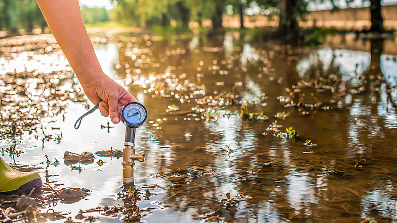
Model MCM-02 Dwarf Mulines are used to measure water velocity in shallow waters. Where the dwarf muline is used; Dwarf mulines are used worldwide for their proven quality, precision and reliability in measuring water velocity in shallow waters. Since it is a light and practical flow meter, it is generally preferred when measuring flow in shallow waters in remote areas. Very precise two-bearing shaft, min. 0.025 m/sec. with max. 5 m/s. The most sensitive “water velocity measurement” can be made by means of a “reed contact” at the water flow rate. The water depth at which the Dwarf Muline is used is a minimum of 4 cm.
Assembly
The Dwarf Muline is mounted on a 9mm diameter spindle.Dwarf Muline, which is designed as a sleeved tube as a very useful and sensitive device, works in harmony with the electronic meter during measurement. The muline body is made of brass, the propellers are made of aluminum, and the measuring handles are made of chrome. The hull and propellers are Nickel plated. In places where the water level is higher, it is recommended to increase the diameter of the clamping rod to 20 mm to make a healthy measurement.
Working Characteristics of Propellers
Depending on the different speed ratios, propellers with different pitch values are used. Propellers are integral parts. Depending on the flow and speed of the water, which propeller will be used at the correct speed according to its angular values is given in Table 1. The propellers selected depending on the flow and speed operate in accordance with the cosine/precision principle with an accuracy of ±1% of the measurement value.
Handle
9mm. in diameter, 1.5 m.in length, 50 cm. 3-part, with base iron and numbered every 5 cm.
Cable
The number of revolutions that appear with the rotation of the propeller in the water is transmitted to the numerator via the connection cable (2 m.). The plugs on the cable ends are made of stainless chrome material.
Calculating Flow Rate
The flow rate of the water is obtained according to the number of revolutions to be obtained as a result of the rotation of the propellers. The k and Δ parameters in the v = k.n + Δ formula used to obtain the velocity are determined while calibrating the instrument. These parameters and the "abak" values showing the speeds coming to the "n" revolution number were copied to the memory of the electronic numerator device and given as a report.
v = k.n + Δ
v = velocity of water (m/sec.)
k = hydraulic gradient covered by the propeller in the water (m)
n = Average of the propeller revolutions per second
Δ = characteristic of the Universal Muline relative to values obtained from tests in an open calibration channel (m/sec.)
Since there are mechanical differences between the mulines in the propeller and shaft bearing, the fixed values k and Δ are found by special tests in the special calibration channel (DSİ-TAKK). Calibration values are given in table with mulineOperating temperature | -20°C to +80°C |
Accuracy | Time : 0.01sec Number of Pulses : 1 pulse |
Max. Number of Pulses | 40puls/sec |
Time setting | 5 , 10 , 15 , .... 200 sec |
LCD Screen | 128x64 Graphics Dot Matrix |
Keypad | 6 Keys Keypad |
Battery | 3.7V Lithium Ion |
Interface | USB (used to charge the battery) |
Protection | IP65 |
Weight | 430 gr |